
The Viterbi is a split ortholinear mechanical keyboard of 70 switches arranged in two 7x5 blocks. It is sold as a kit on keebio.com; you cannot buy this keyboard in a store. There are assembly services around the web and from the store itself, but most of the fun comes from sourcing all the parts and building the keyboard. You can also buy similar keyboards (especially the Iris) through various local groups in Manila.
This post will go over testing components, the build experience, materials, flashing, and using the keyboard.
Materials, costing, and shipping
Materials are easily sourced online. Shipping outside of CONUS (Continental US) is the typical concern. My advice for the US-only stuff: get a freight forwarder.
Moving on, here are the materials:
From keeb.io
| Item | Price | Notes |
| Viterbi Rev 2 Kit | 1060.3 Php | |
| Peel-a-way Sockets | 53.015 Php | 1 strip |
| TRRS cable | 212.06 Php | Cheaper elsewhere |
| Black Aluminum Plates | 1590.45 Php | |
| Delivery (MyShoppingBox) | 438.97 Php | 8.28 USD total due to promos |
From various sellers on shopee:
| Item | Price | Notes |
| Per key LED | 121.8 Php | 70 pcs, Blue |
| Pro Micro Clones | 440 Php | 2 pcs |
| *LED Strip | 105.93 Php | 14 pcs, still uninstalled |
| Delivery | 150 Php~ | Rough estimate |
From kbdfans.cn:
| Item | Price | Notes |
| Kailh Speed Bronze Switches | 999.6 Php | 70 pcs; 19.60 USD |
| Delivery (Express) | 765 Php | 10 — 15 USD |
From Alexan (Megamall):
| Item | Price | Notes |
| Resistors | 40 Php~ | 510 ohms; 70 pcs; rough estimate |
total cost: 5977.125 Php (roughly 115-120 USD)
For a cheaper build, consider:
- using free shipping from kbdfans as their shipping is reliable anyway;
- joining group buys (but always compare before joining);
- buying cheaper FR4 plates at 25 USD or sourcing plates locally;
- and recycling old switches.
PCB design
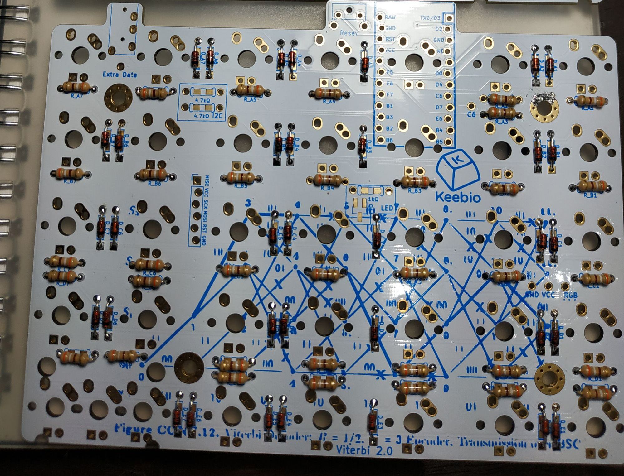
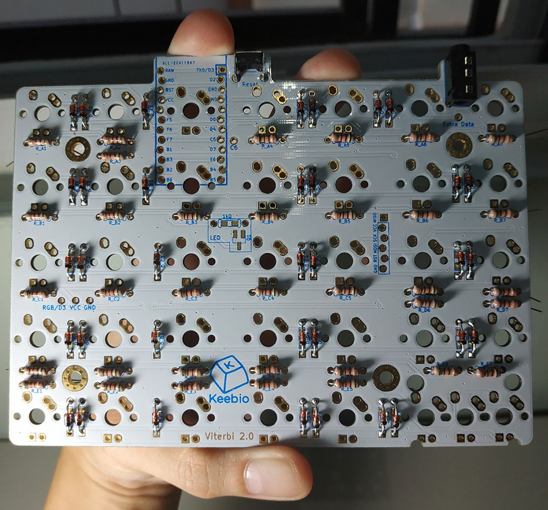
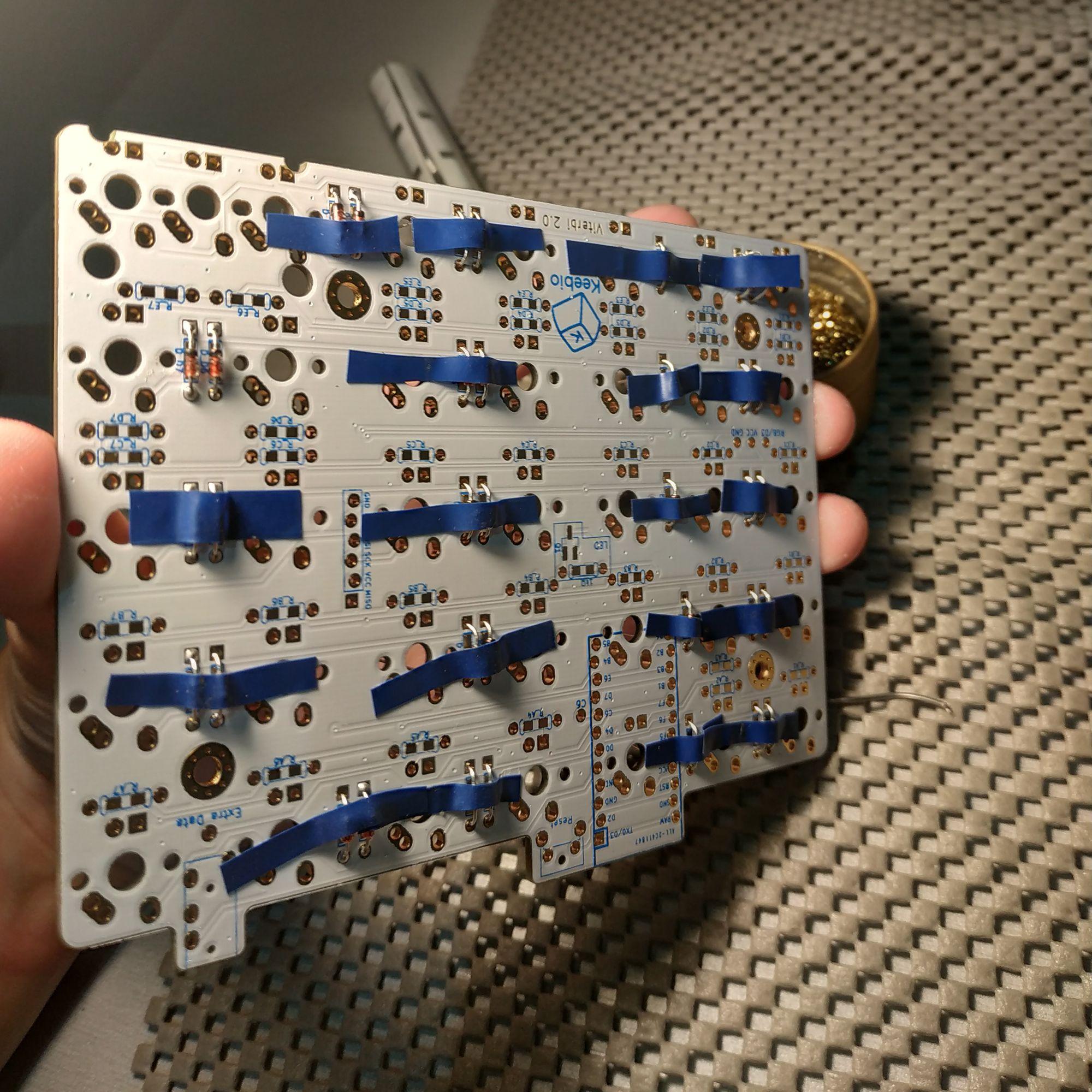
The PCB is a thoughtfully designed product made with builders in mind. When working with split ortholinears, their mirror appearance lends themselves to common mistakes including placing diodes on the front orientation, switching left/ride sides, and general confusion about which way to orient the Pro Micros. To address this, there are several improvements over the older model:
- The second iteration has made it clear what the front and back are. Pictured below is the bottom/back.
- The pro micros are now oriented only one way (originally, the left and right sides had flipped pro micros).
- The labels are written on the side that the component's pins should go through.
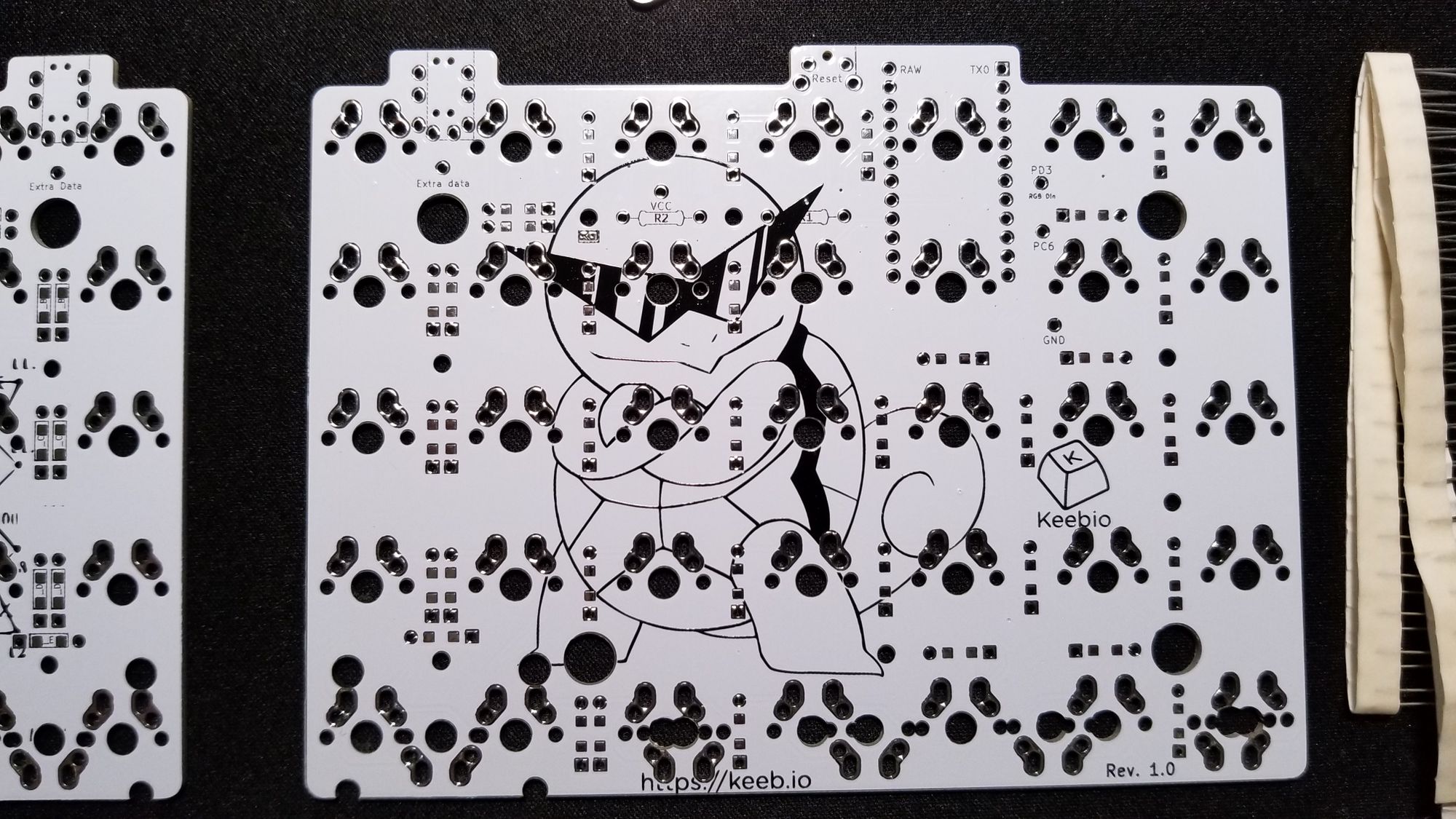
As a minor note, the Squirtle Gang illustration was removed in Viterbi Rev 2 (probably to make way for the informational markers).
Build process
One of the biggest hurdles I had as a level zero builder was that my multimeter was too old to have a diode testing mode. I gave up after a lengthy five minutes of head-scratching and chucked it back in the drawer. Instead I got two bits of wire, a 9-volt battery, and a breadboard.
A summary of the process is as follows:
- If you don't have a multimeter, test and/or flash all the components and microcontrollers.
- Add epoxy to each microcontroller's USB port. While this isn't a guarantee that the port won't snap off, it provides a layer of protection.
- Solder the diodes, resistors, and other components except the switches, LEDs and Pro Micros.
- Socket the Pro Micros and start testing switches.
- Solder the switches.
- Solder the LEDs; fit/friction test before soldering.
- Add keycaps.
Test all the things
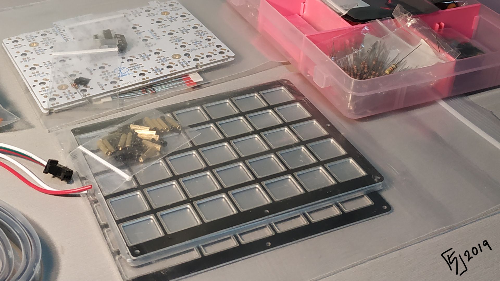
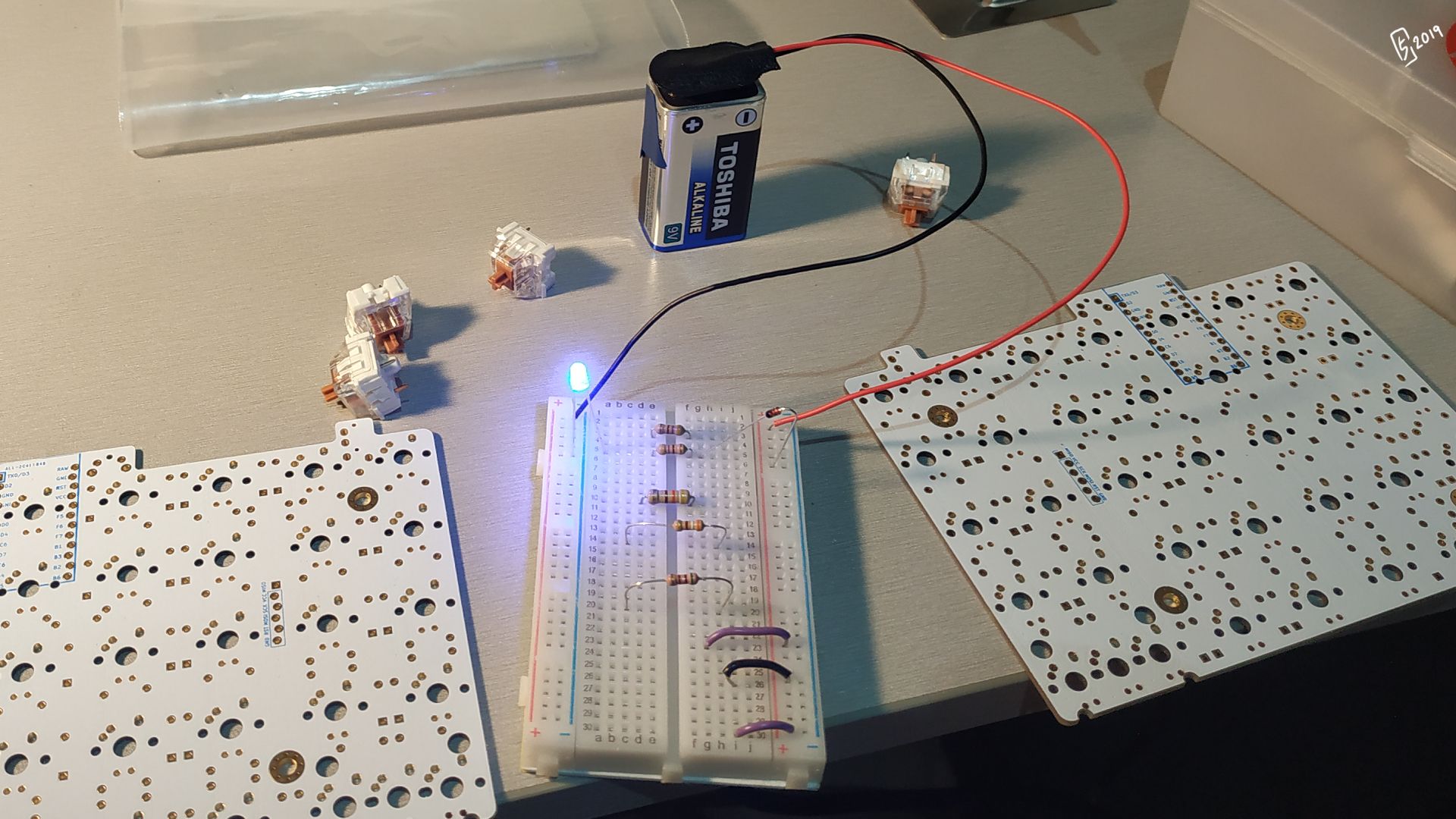
Set up the breadboard's circuit by putting one end (+/-) of each wire on the power strips (on the far left and far right columns) on the same row, on the correct polarity.
You can then test a LED with a resistor, and add/remove components depending on how many components you want to test at one time.
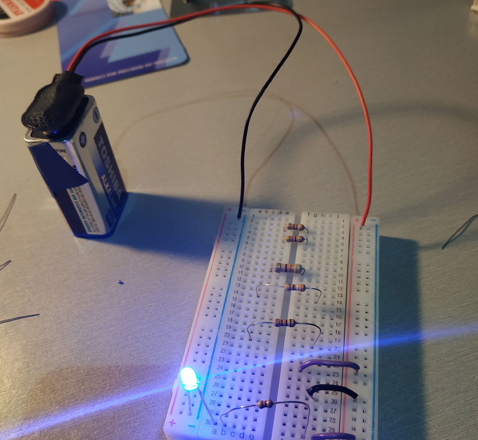
In the above example, I just need to have a wire to connect the (+) current to the main breadboard. I close (complete) the circuit by putting the positive leg (longer) of the LED on the middle column of the breadboard and the negative leg (shorter) on the negative power column. The LED should light up.
If at first it doesn't light up, try changing the orientation of the LEDs and diodes or lessening the components tested before assuming a faulty component.
Total time: about an hour
Flash and glue all the things
The micro USB ports of Pro Micro clones tend to break at the slightest twitch of the cord. Glue the bastards down with some epoxy after covering the connectors with some electrical tape to keep the epoxy from seeping into the connector.
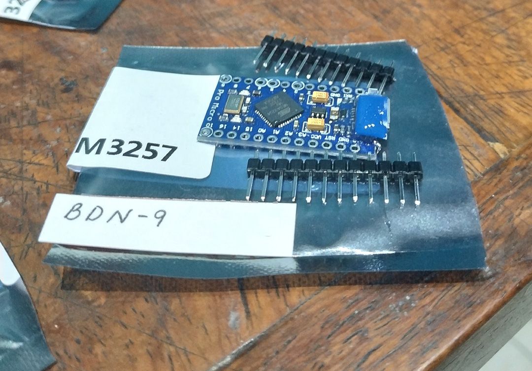
You then have to flash the two microcontrollers. The firmware for this is QMK, which can be cloned or downloaded from Github (more on flashing in a future dedicated post). On Windows, flashing is achieved through QMK Toolbox in theory. However, the software sometimes fails to detect the chips in time to put them into bootloader mode, so our elevator to the finish line must be abandoned in favor of going up the stairs. The true use of QMK Toolbox when this happens is to download your keyboard's keymap file and to print out the command you need to flash, which you will paste into cmd.
- Enter cmd (winkey+r) and look for the QMK folder (dir + cd commands).
- Paste and press Enter to run the command from QMK Toolbox. It will fail; the point is to have easily recalled by pressing Up during those few seconds the chip is in bootloader mode.
- Attach the chip's micro USB port to the cord (don't connect to the computer yet)
- Stick a bit of wire (or paperclip, or tweezers) into both the Boot0 and Reset pins on your microcontroller. This is called shorting.
- While keeping those bits of wire on the pins, connect the USB to the computer.
- Remove the wires from the microcontroller.
- The chip will be in bootloader mode for a few seconds, which will allow you to flash. Press Up to call up the last command (the one from QMK Toolbox) on the console then press Enter to run the command.
- Hopefully you get the success message on the command line.
Total time: 1'30"
Start soldering all the things
If you, like me, have gone through life without having to solder, then your best bet is to warm up on some stripboards. I have no idea what these are called colloquially but they can be found in Alexan Megamall.
My working temp was about 325 - 350C. At that temperature you should be a little aware that keeping the heat on for too long will lift the circular conductive ring (pads) you're supposed to be soldering the parts to.
The diodes took me 4 hours; 2 on each side. I was going extremely slowly as I did this; most videos on youtube show it is doable with good tools in an hour for each side.
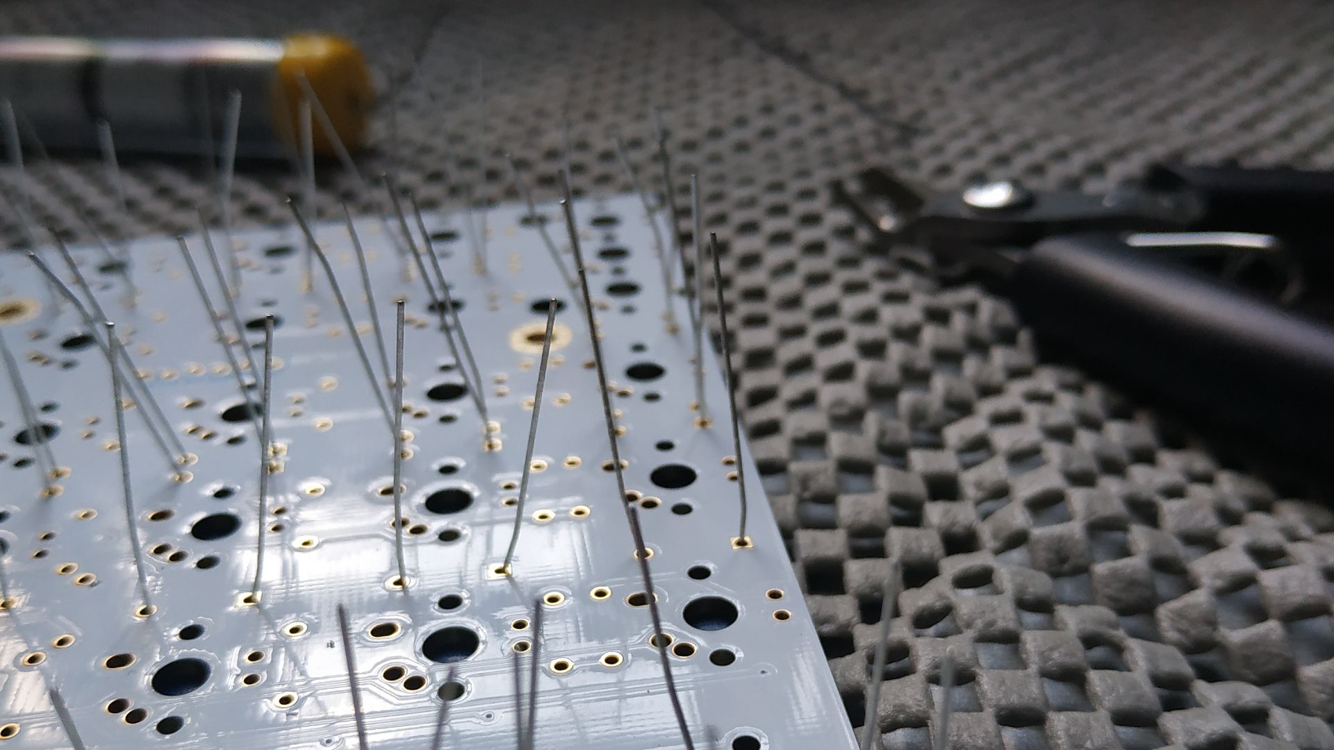
About through-hole soldering: My beginner's work bench lacks a PCB holder. I have an anti-slip mat and it doesn't help keep components flush to the PCB (some of them were raised and had to be redone). Also, I burned parts of the mat when soldering.
The resistors took me another 4 hours; 2 on each side. They were 510 ohm resistors and looked huge next to the diodes.
Another newb issue: aesthetic. I wanted to keep the pins straight and not bent as I soldered them, so I spent on electrical tape to keep them in place rather than bent. The results were questionable as not all the electrical tape stuck consistently, meaning that some diodes lifted a little above the board.
I then soldered the MOSFET — damn if that thing isn't tiny — then the extra resistors for I2C communication, the Peel-A-Way sockets, reset button, and the Pro Micros. That took about an hour for each side.
The advantage of socketing (with Peel-A-Way or Mill-Max) is in being able to rip off any broken microcontrollers any time. It is highly encouraged.
The legs from the diodes were reused as the pins for the Pro Micro. Legs from LEDs are too big.
Before soldering the switches, I tested them. It took about 1.5 hours for each side for testing and soldering.
Then I worked on the LEDs. I started with the LEDs directly under the microcontrollers. Therein began my four-hour pain in the ass.
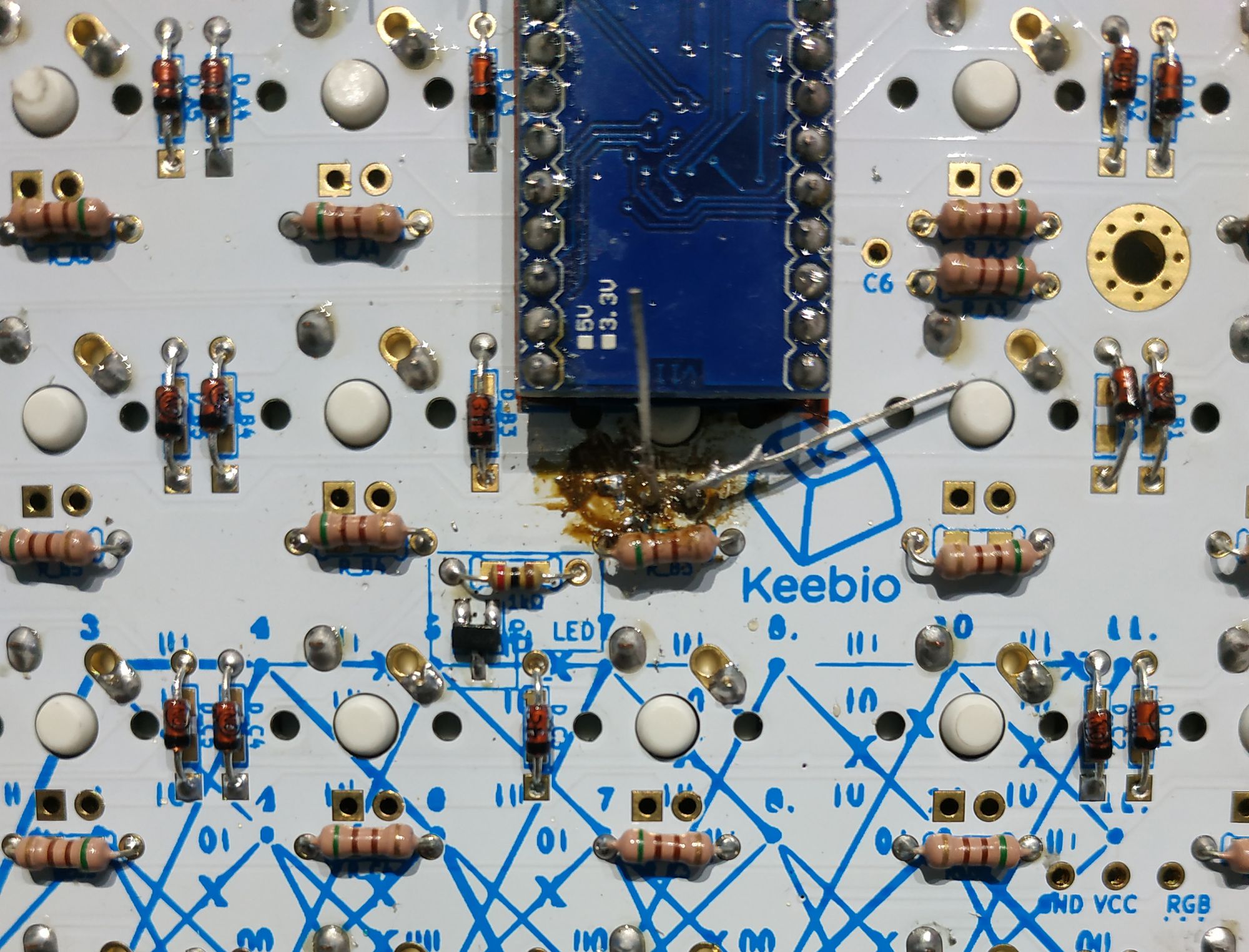
I screwed up the orientation on one of the LEDs. Getting the LED out itself with one iron was hard (I could not lift both legs at the same time). I lifted the pads with all the effort and strain and still couldn't figure it out. I eventually went with the slap method — I heated one leg and banged the PCB on the table. It raised the LED head a bit and I cut off the head, allowing me to remove each leg individually.
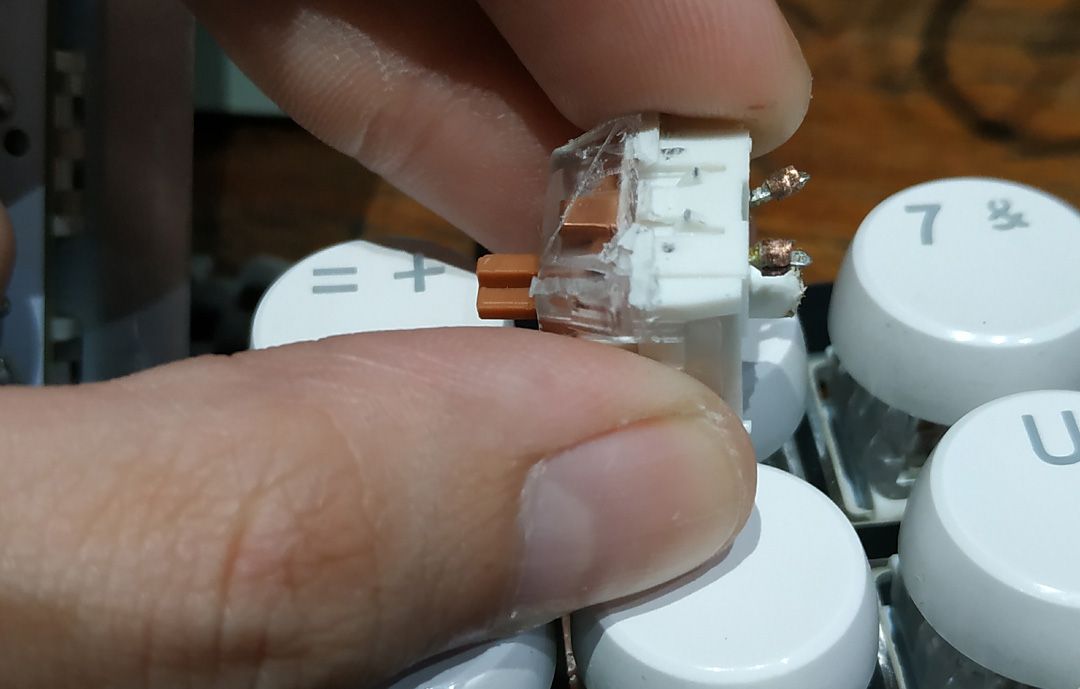
I then had to yank the switch out with brute force and replace it with another. The switch came off with what appeared to be copper/solder gunk; the pad miraculously still worked.
After that, I made sure to test the LEDs before soldering them, thus completing the build with all switches working.
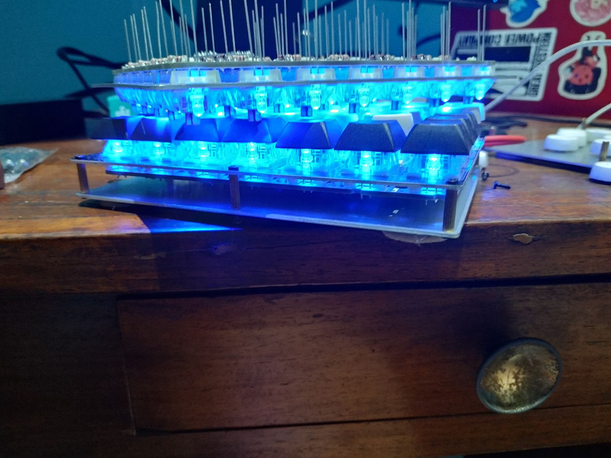
Total time: 16' for pure build time; plus/minus a few hours in despair
Moving forward
Pro Micros are cheap in the Philippines, but their weak point at the port can still break. Even with properly cured, properly mixed epoxy. Even with a magnetic cable. Have a back up.
If you are too cheap to pay for a multimeter, loupe, third hand, and all the nice desoldering tools, you have to build very carefully and compensate with experience. My takeaway was that I should never start soldering the switches until I've verified the RGB underglow (the last part of all the bottom side components) and the socketing.
Fit-test or breadboard-test all the things before soldering if you can. This is the only compensation you can make when you don't have a multimeter.
Keep any extras or bits of metal (such as the legs) that have been clipped off.
Good luck and till the next build!

